Today I had some time and while tidying up, I found a set-top box we got some time ago from our Internet provider. It came with a contract for combined 50Mbps fiber connection and IPTV.
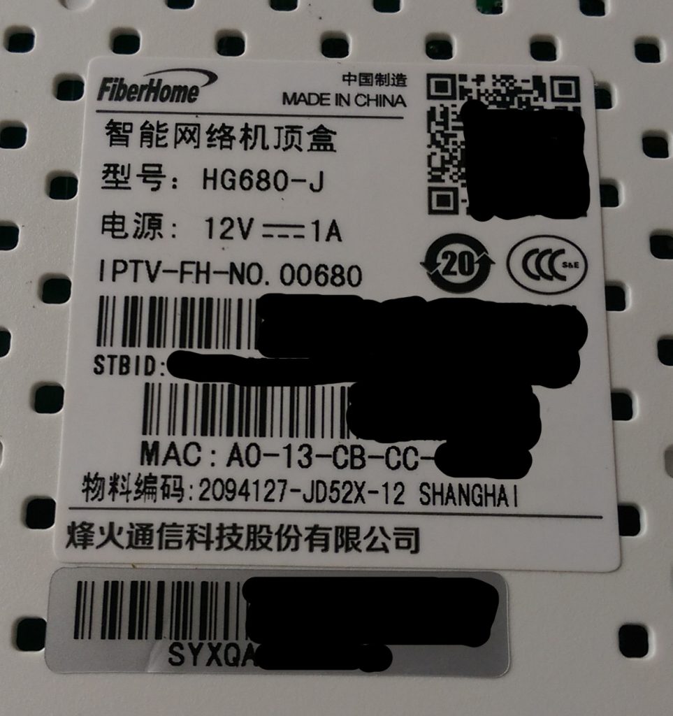
The guy who installed the IPTV box (labeled FiberHome HG680-J) showed us that it worked, but afterward we tried once and did not get it to work, because it did not want to connect to the network. We lost interest and since then it's sitting next to the TV and is not used. So today I got curious about the contents of this little box and decided to open it and share the findings with you.
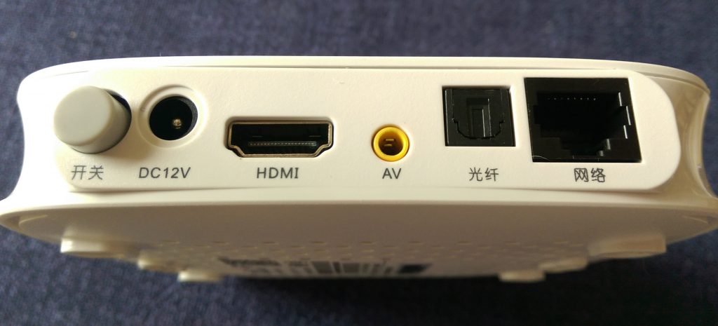
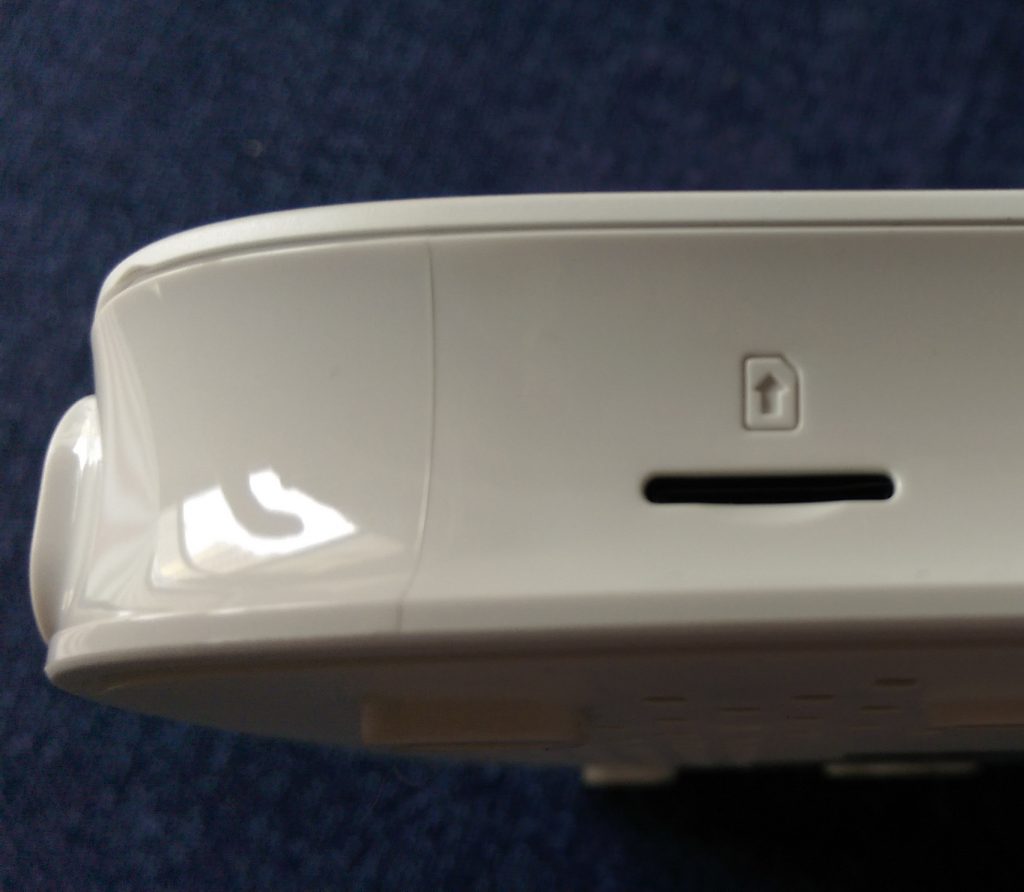
That's the box and the connections on four sides:
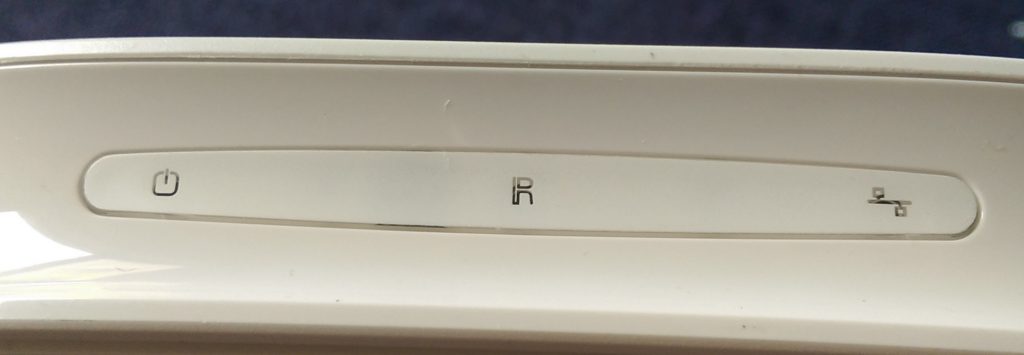
- Front: Power LED, Network Led, IR Receiver
- Left: Micro SD Card slot
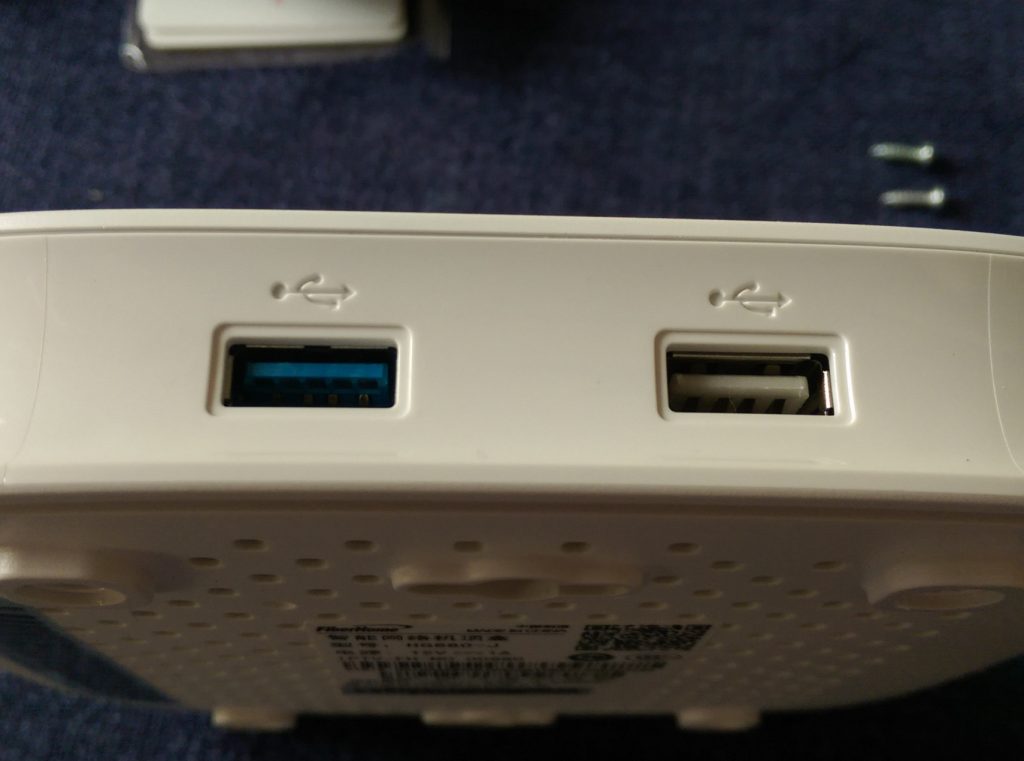
- Right: Two USB connectors, one blue, so perhaps USB 3
- Back: Ethernet RJ45, SPDIF, AV 3.5mm connector, HDMI, DC 12V and power switch
But now the more interesting part about what's inside. You can easily open the box. There are four screws under the rubber feet. Remove the feet and the screws and you can pry open the lid.
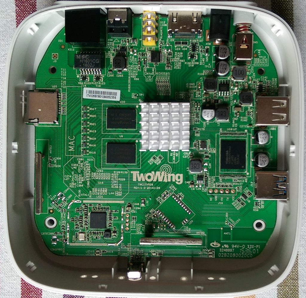
Here two pictures with the labeled main components on the PCB.
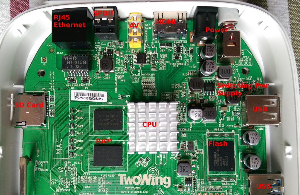
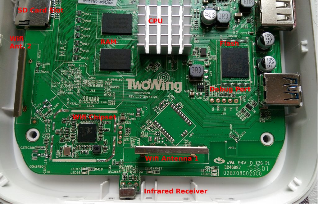
I think it's really interesting to see how this box has a very similar design to most of the small Arm-based SBCs (Single Board Computers) available now, like the Raspberry Pi, Banana Pi, etc. You can see that it's a highly integrated CPU, additional flash memory and RAM (probably two times 256MB guessed from the IC marking NANYA NT5CB256M16CP) and a separate wifi chip RTL8192EU.
Sadly the heatsink is glued to the CPU, so I cannot find any hint at the moment about the type of CPU used in this box. If the one blue USB connector really speaks USB3, I guess this indicates that the used CPU is a bit more fast that a Raspberry Pi.
Near to the CPU and flash there are five test points labeled NC, GND, RX, TX and VCC. This looks very much like a serial console connector. And I have neither a UART level converter not an oscilloscope available here to have a look at the signals. :-(
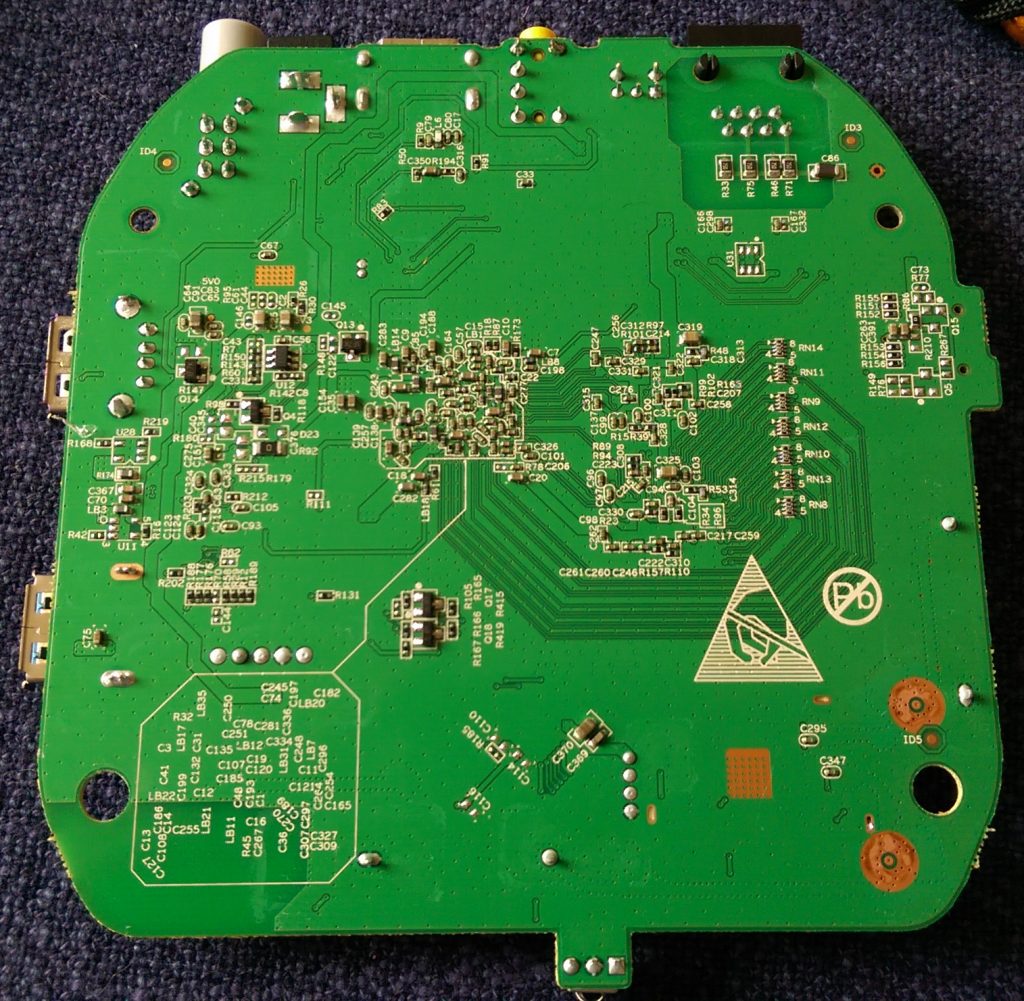
The bottom side of the PCB does not contain any interesting things:
